-

sales@tujinmagnet.com
-

+86-18858010843

Content
A servo motor engineer opens the incoming magnet test report and looks for one curve long before he checks any other number: the intrinsic demagnetization curve at 150 °C. That curve, which is the working segment of the hysteresis loop, tells him whether the rotor will hold its flux after the thousandth full-load transient. A loop that bends too early at temperature usually means the motor draws more current, loses torque, and produces more heat than the production acceptance limit allows. For every design engineer and purchasing specialist responsible for magnetic components, the hysteresis loop is the most important specification a NdFeB magnet manufacturer can publish. It contains the remanence that defines magnetic flux, the coercivity that defines stability against demagnetization, and the energy product that defines the physical size of the motor.
This guide explains the hysteresis loop from the perspective of practical magnet specification, motor design, and supplier evaluation. We will cover the meaning of the B-H curve, the physical origin of magnetic hysteresis, the parameters that motor engineers actually use on datasheets, the effect of temperature on the loop, and the measurement methods behind the numbers. By the end, you will know exactly which questions to ask a custom magnet supplier before committing to a production order, and why a magnet grade name alone is never a sufficient specification.
A hysteresis loop is the closed, history-dependent curve that a magnetic material traces when the magnetizing field is cycled between positive and negative saturation. On a standard graph, magnetic flux density B appears on the vertical axis and magnetic field strength H appears on the horizontal axis. For ferromagnetic materials such as sintered neodymium-iron-boron, the relationship between B and H is nonlinear and irreversible: the same value of H produces different values of B depending on whether the field is increasing or decreasing, and on how far the material has traveled around the loop.
To understand how the loop forms, start with a fully demagnetized sample. As H increases from zero, B rises along the initial magnetization curve until the material reaches saturation. Reducing H back to zero leaves a residual flux density known as remanence, Br. To bring B to zero, the field must reverse direction and reach the normal coercivity, Hcb. Continuing to negative saturation, reversing again, and returning to positive saturation completes the mirror-image halves of the loop. The area enclosed by this closed curve represents energy converted into heat during one complete magnetization cycle.
Magnetic hysteresis in a ferromagnet is essentially rate-independent: the static shape of the loop changes little with the speed of field variation, which is why the datasheet curves published by permanent magnet manufacturers remain valid across a wide frequency range. In a real motor, eddy currents add rate-dependent losses on top of the static loop, but the magnet's own B-H behavior still follows the same static curve. The history dependence is the key idea: the loop is a record of all irreversible domain events, and any operating point inside the loop can only be reached by following a specific path from saturation.
For permanent magnets, engineers rarely work with the full loop. A magnet inside a motor operates in the second quadrant, where H is negative and B remains positive. This is the demagnetization region, and it is the only part of the loop that determines whether the magnet keeps working under load. The shape of the second-quadrant curve, not the full loop, is what separates an ordinary magnet from a high-performance motor magnet.
Key takeaway: The hysteresis loop is the magnetic memory of the material; its second quadrant is the working zone that defines permanent magnet stability.
When a permanent magnet is placed inside a motor, it does not cycle along the whole loop; it stays in the second quadrant, where the operating point is defined by the intersection of the magnet's demagnetization curve and the load line of the magnetic circuit. The first quadrant of the loop matters for magnetization but not for operation. This is why every serious NdFeB magnet datasheet presents the second-quadrant B-H curve and the intrinsic J-H curve as the primary data for motor design.
Datasheets for sintered NdFeB magnets usually present four headline numbers, and all four are direct consequences of the hysteresis loop. The chart below compares the typical maximum energy product (BH)max of the four permanent magnet families most commonly used in industrial motors. (BH)max is the largest rectangular B x H product that fits inside the second-quadrant portion of the demagnetization curve, and it is the most widely used single proxy for magnetic strength. Motor designers rely on (BH)max to rank candidate materials before a single stator is laminated. The values plotted are representative upper-band figures from commercial sintered magnet production, not laboratory records.
Sintered NdFeB leads by a wide margin; at 52 MGOe it offers roughly 60 percent more energy product than the strongest samarium-cobalt grades. That gap explains why NdFeB dominates traction motors, servo motors, and robot joint drives, where a small rotor diameter and high torque density are non-negotiable. A smaller magnet volume also reduces rotor inertia, which improves dynamic response in servo applications. However, a high (BH)max does not automatically mean a safe motor design. The second quadrant of the loop must remain linear down to the worst-case operating point; otherwise, part of the magnet irreversibly demagnetizes every time the inverter applies a current spike. Samarium-cobalt, with lower (BH)max but considerably higher coercivity at elevated temperature, remains the first choice for aerospace generators and other systems exposed continuously above 250 °C. AlNiCo magnets retain impressively high remanence, yet their coercivity is so low that a moderate armature reaction can wipe out the magnetization, which is why they rarely appear in variable-speed motors. Ferrite has a substantially smaller loop, so ferrite motors compensate with larger diameters and higher pole counts. For purchasing teams, this chart explains a familiar sourcing pattern: the two materials most often specified for motor magnets sit at opposite ends of the coercivity spectrum. The final material decision is therefore never made on (BH)max alone. A competent permanent magnet manufacturer publishes demagnetization curves at 20, 60, 100, 120, 150, 180, and 200 °C so the designer can confirm that the loop stays square at the real operating point. That level of documentation is the difference between a catalog magnet and an engineered magnetic component.
| Parameter | Symbol | Meaning in the loop | Typical sintered NdFeB range |
|---|---|---|---|
| Remanence | Br | Flux density remaining after saturation with H = 0 | 1.05-1.45 T |
| Normal coercivity | Hcb | Reverse H needed to bring B to zero | 750-900 kA/m |
| Intrinsic coercivity | Hcj | Reverse H needed to bring polarization J to zero | 955-2388 kA/m |
| Maximum energy product | (BH)max | Largest product of B and H inside the second quadrant | 25-52 MGOe (200-414 kJ/m3) |
The first three rows of Table 1 map directly onto the hysteresis loop. Br is the intercept on the B axis when H returns to zero. Hcb is the intercept on the H axis when B reaches zero. Hcj is measured from the intrinsic curve and reflects the field strength required to destroy the material's internal polarization completely. Hcj is always larger than Hcb, and it is the critical parameter that guards against demagnetization in demanding motor applications. A motor designer who reads only Br and (BH)max misses the real risk: a magnet with strong flux but low Hcj may fail precisely when the motor needs it most, under peak current and maximum temperature.
Key takeaway: Read the full second-quadrant curve, not just the four headline datapoints; two magnets with identical Br can have completely different resistance to demagnetization.
Ferromagnetic materials are composed of magnetic domains, which are microscopic regions with uniformly aligned magnetization. In an unmagnetized block, domains are oriented randomly and the net external flux is near zero. When an external field is applied, favorably oriented domains grow at the expense of their neighbors, and the walls between domains move through the crystal lattice. Some of this displacement is reversible; remove the field and the walls spring back. At higher field levels, domain walls overcome pinning sites such as grain boundaries, second-phase particles, and lattice defects, and the magnetization rotates irreversibly into new orientations. When the field is removed, these domains remain in their new configuration, which is why the demagnetization curve does not retrace the magnetization curve.
The strength of irreversibility is governed by magnetocrystalline anisotropy. In sintered NdFeB, the Nd2Fe14B phase has a strong uniaxial anisotropy that forces magnetization to align with the easy axis. If a reverse field is applied, the magnetization resists rotation until the field overcomes the anisotropy energy, and then whole grains flip abruptly. This abrupt rotation is the source of both high coercivity and loop squareness. The finer and more uniform the grain structure, the more abruptly the grains switch, and the squarer the second-quadrant curve appears.
Modern magnet manufacturers control coercivity at three levels: composition, microstructure, and grain boundary engineering. Adding heavy rare-earth elements such as dysprosium or terbium raises the anisotropy field and therefore Hcj, but it also reduces Br. A finer, uniform grain size increases coercivity by adding more grain boundaries that act as pinning sites. The most important process is grain boundary diffusion (GBD), where a thin layer of heavy rare-earth elements is diffused along the grain boundaries to decouple neighboring grains magnetically. This allows a manufacturer to raise Hcj significantly while keeping Br loss small, which is exactly what high-temperature motor grades require.
The result of these processes appears on the datasheet as loop squareness, usually expressed as Hk/Hcj, where Hk is the field at 90 percent of Br on the demagnetization curve. A high squareness ratio, typically above 0.90, means all grains reverse at nearly the same field. A low ratio means a gradual spreading of switching fields, which produces a kinked loop and a higher risk of partial demagnetization under transient loads. For servo motors and robot joint drives, where torque linearity depends on stable flux, squareness is as important as peak coercivity.
Key takeaway: The loop shape is the visible fingerprint of the magnet's microstructure; a square loop is an engineering achievement, not a coincidence.
The operating point of a magnet inside a motor is determined by the permeance coefficient, Pc, which is the slope of the load line drawn on the B-H diagram. Pc is defined as B divided by u0 times H, and it is largely set by the magnet's length-to-area ratio and the reluctance of the surrounding magnetic circuit. The magnet sits at the intersection of this load line and the second-quadrant demagnetization curve. Under load, armature reaction applies an external demagnetizing field, and the operating point moves down the loop. If a current spike or an elevated rotor temperature pushes the operating point beyond the knee of the curve, the magnet suffers irreversible flux loss and never fully recovers.
This is why a motor engineer does not choose a magnet grade simply by Br and (BH)max. The selection process is driven by the worst-case combination of temperature, peak phase current, flux-weakening demand, and rotor geometry. The table below summarizes the main hysteresis-loop concerns for typical motor categories and the grade families that address them.
| Motor application | Main hysteresis-loop concern | Typical grade choice |
|---|---|---|
| EV traction motor | Irreversible demagnetization under peak phase current at 150-180 °C | UH, EH (Hcj greater than or equal to 2000 kA/m) |
| Industrial servo motor | Square second quadrant for linear torque control and low torque ripple | SH, UH |
| Compressor PMSM | High steady-state rotor temperature from winding and gas heat | H, SH |
| BLDC fan motor | Cost-sensitive; coercivity must still exceed demagnetizing field at 100 °C | N, M, H |
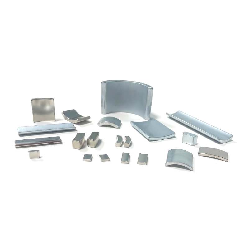
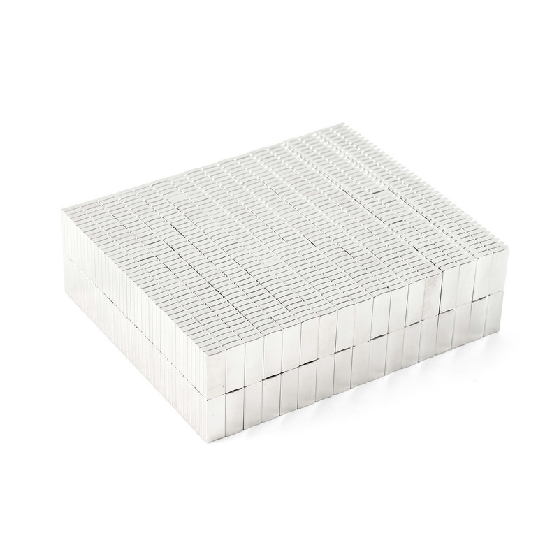 Neodymium Arc and Segment Magnets for Motor ApplicationsThis product range covers arc and segment neodymium magnets used in DC, BLDC, servo, and traction motors. The surrounding discussion highlights how rotor geometry and operating point affect loop selection, making these shaped magnets directly relevant to motor design decisions.View Product →
The rotor architecture also changes how the loop is used. In surface-mounted permanent magnet (SPM) motors, the magnet sits directly in the airgap, which lowers the permeance coefficient and puts the operating point closer to the knee. In interior permanent magnet (IPM) motors, the magnet is buried inside the rotor laminations, which increases Pc and stabilizes the operating point but also exposes the magnet to stronger demagnetizing fields during flux weakening. The two approaches require different loop strategies, as shown below.
Surface-mounted (SPM)Magnet exposed to the full airgap reluctance, so Pc is low and the operating point sits high on the demagnetization curve. A square loop with high Hcj is essential to survive current transients. Arc magnets are the standard form, and the magnetization direction must be radial or parallel depending on pole count. |
Interior-mounted (IPM)Magnet buried in laminations enjoys a higher Pc and a more stable operating point. However, flux-weakening currents at high speed create strong opposing fields along the magnet axis. This demands UH or EH grades and careful control of the knee position at the maximum inverter temperature. |
The loop's squareness also affects torque ripple and back-EMF harmonics. A magnet with a gradual, sloped transition near the knee will produce a slightly distorted airgap flux waveform, which translates into additional harmonic content in the motor's back-EMF and higher cogging torque. In high-precision servo applications, this distortion shows up as velocity ripple that the controller must constantly correct, wasting energy and accelerating bearing wear. A manufacturer that controls the loop squareness of every batch can keep these harmonics low without extra cost to the motor builder.
When the motor design is finalized, the engineer should request the actual demagnetization curves from the magnet supplier and simulate the operating point at the worst-case current angle and temperature. A manufacturer that documents this level of detail typically publishes its measurement and tolerance policy in the permanent magnet technical data center, along with process flow, coating options, and size tolerance limits.
Key takeaway: The hysteresis loop is the boundary condition for every motor performance calculation; the operating point must stay above the knee at all times, and the loop's squareness determines how stable that operating point truly is.
The area enclosed by a hysteresis loop is the energy dissipated as heat during one complete magnetization cycle per unit volume of material. In electrical steel laminations, this hysteresis loss is one of the major components of core loss in rotating machines. The empirical Steinmetz equation, Ph = eta x f x Bm^n, describes how hysteresis loss scales with frequency f and peak flux density Bm. The exponent n typically lies between 1.5 and 2.2 for common silicon steels, which means that doubling the flux density can more than triple the hysteresis loss.
In permanent magnet motors, the magnets themselves usually sit at a fixed operating point and do not experience continuous magnetization cycles, so the magnet's own hysteresis loss is small during steady operation. The stator core, however, is cycled at the electrical frequency, and its loop area determines a significant portion of the no-load loss. In IPM motors with deep flux weakening, the magnet operating point can move noticeably with speed and torque, producing small loop excursions that add to the total loss. This is why motor efficiency classes such as IE4 and IE5 depend not only on magnet grade but also on the quality of the stator laminations and the precision of the magnetization pattern.
Hysteresis loss also matters outside the motor itself. Magnetizing fixtures used to magnetize and calibrate rotors must overcome the loop of every magnet before it reaches saturation, so the fixture design directly depends on the loop area. In magnetic hysteresis brakes and torque limiters, the loop area is the actual working parameter: the brake torque is proportional to the energy absorbed per revolution. For most motor magnet applications, however, the priority is not narrowing the magnet's loop but keeping the second quadrant high and square.
| Loss component | Physical mechanism | Relationship to the loop | Typical reduction method |
|---|---|---|---|
| Hysteresis loss | Domain wall pinning and irreversible rotation | Proportional to the area of the static hysteresis loop | Grain-oriented steel, thinner laminations, lower flux density |
| Eddy current loss | Circulating currents induced by alternating flux | Scales with frequency squared and thickness squared; independent of loop area | Laminated cores, segmented magnets, higher-resistivity steel |
| Excess (anomalous) loss | Micro-eddy currents around moving domain walls | Adds to the static loop area and grows faster at high frequency | Improved material processing, reduced grain size |
Key takeaway: For a permanent magnet, the relevant loop characteristic is its position and squareness, not its area; for the steel core around it, the loop area is a direct and permanent efficiency tax.
Both Br and Hcj of NdFeB decrease as temperature rises. Br drops roughly linearly at a rate of about 0.12 percent per degree Celsius for standard grades, while Hcj drops faster. The knee on the intrinsic demagnetization curve moves upward toward the operating point as temperature increases, shrinking the safety margin of the motor. At the same time, the magnet's recoil permeability may rise slightly, which means the motor's back-EMF will fall with temperature much faster than a linear coefficient alone would suggest.
Magnet grades are classified by their maximum continuous working temperature, from N-series at 80 °C to EH-series at 200 °C. The trade-off is that raising Hcj requires heavy rare-earth elements such as dysprosium or terbium, which increase material cost and slightly lower Br. The table below gives representative temperature coefficients for the practical grade series used in motor production.
| Grade series | Maximum continuous working temperature | Br temperature coefficient | Intrinsic coercivity temperature coefficient |
|---|---|---|---|
| N | 80 °C | -0.12 %/°C | -0.60 %/°C |
| M | 100 °C | -0.12 %/°C | -0.58 %/°C |
| H | 120 °C | -0.11 %/°C | -0.55 %/°C |
| SH | 150 °C | -0.10 %/°C | -0.50 %/°C |
| UH | 180 °C | -0.10 %/°C | -0.45 %/°C |
| EH | 200 °C | -0.09 %/°C | -0.40 %/°C |
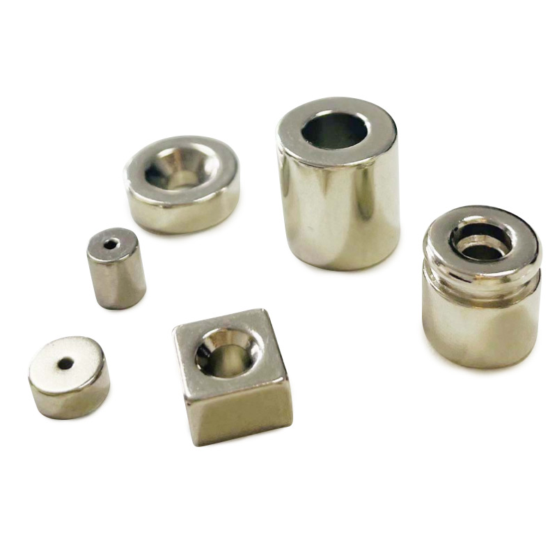
For ring magnets mounted on a rotor shaft, heat from the windings and bearings attacks the inner diameter first, which is exactly where the demagnetizing field is hardest to control. This is why high-temperature ring magnets are specified in SH, UH, and EH grades for sealed compressor motors, traction motors, and other enclosed drives. A motor designer should always compare the demagnetization curves at the actual operating temperature, not simply extrapolate from room-temperature values using the coefficients.
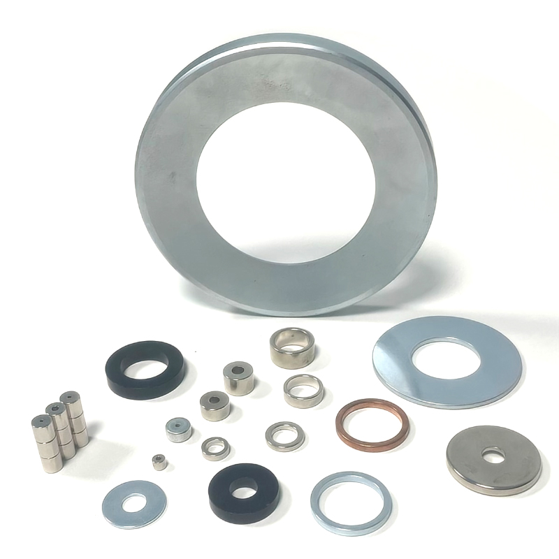
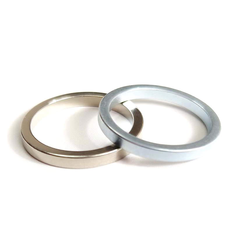 High-Temperature Neodymium Ring Magnets for Motors and CompressorsFeatured are neodymium ring magnets suited for motors, speakers, generators, and sensors. The preceding text emphasizes thermal effects on the inner diameter and specifies SH, UH, and EH grades, so these ring options are key for enclosed drives requiring documented loop behavior at elevated temperatures.View Product →
The hysteresis loop at temperature is the curve that should appear on the supplier's test certificate, not merely the room-temperature curve. In practice, a manufacturer measures demagnetization curves at several temperatures using a high-temperature permeameter or a vibrating sample magnetometer with a heating stage. The curves should include the knee field Hk, the squareness ratio Hk/Hcj, and the exact position of Br at each temperature. A supplier that can document loop behavior at 150 °C and 180 °C gives the motor manufacturer the data needed for worst-case analysis without guesswork.
Thermal aging should also be considered separately from the instantaneous loop. Even at temperatures below the grade limit, prolonged exposure can cause oxidation along grain boundaries, slightly reducing Hcj over time. Coating quality and production cleanliness therefore influence long-term loop stability. A well-designed magnet with a proper nickel or epoxy coating will maintain its loop shape for the life of the motor, while a poorly coated part may show measurable degradation after only a few hundred thermal cycles.
Key takeaway: The room-temperature loop is a starting point, not a guarantee; always request measured demagnetization curves at the motor's worst-case operating temperature.
The standard laboratory instrument for measuring the hysteresis loop of a permanent magnet is a closed-circuit permeameter, also called a hysteresisgraph. The magnet sample is clamped in an electromagnetic yoke, a Hall probe measures the applied field H, and a fluxmeter coil wound around the sample measures B. The system sweeps H through the required range and plots the complete loop on a computer. Because the magnetic circuit is closed through the yoke, corrections for the demagnetizing factor are minimized, which gives the most accurate representation of the material's intrinsic behavior.
For magnets that cannot be clamped in a yoke, manufacturers use open-circuit methods. A pulse magnetizer fully saturates the sample, and then a Helmholtz coil connected to a fluxmeter captures the total magnetic moment as the sample is withdrawn. For small samples or for research on new alloy compositions, a vibrating sample magnetometer provides precise moment data with a resolution that closed-circuit instruments cannot match. Each method has its own demagnetizing factor correction, which is why two laboratories can measure the same magnet with slightly different results; the measurement method should always be stated on the test certificate.
A complete datasheet should include the second-quadrant B-H curve and the intrinsic J-H curve at room temperature, the same curves at elevated temperatures, and the values of Br, Hcb, Hcj, and (BH)max for each curve. It should also list the knee field Hk, the squareness ratio Hk/Hcj, and the recoil permeability. This is the level of documentation that allows a motor designer to run a finite-element analysis with confidence, because the simulation is only as trustworthy as the input demagnetization data. A manufacturer that controls this data through its process flow and size tolerance system is a far more reliable partner than one that only prints a generic grade table.
The same loop data also governs magnetization patterns. A ring magnet can be magnetized axially, diametrically, radially, or as a multi-pole pattern, and the magnetizing fixture must produce a sufficiently strong field to drive every part of the magnet into saturation along the desired direction. The fixture design is therefore a direct application of loop knowledge: if the magnetizing field is too weak, the magnet will not reach the saturation point on the loop, and the final flux distribution will be uneven.
Flux directed along the cylinder axis; used for encoder rings, magnetic couplings, and small axial-flux generators.
Flux across the diameter; typical for two-pole BLDC fans, speed sensors, and compact pump motors.
Flux pointing outward or inward from the axis; standard for multi-pole rotor rings in servo and traction motors.
Four, eight, or more alternating poles on a single ring; reduces assembly cost and harmonic content.
You can examine the process flow, coating options, and dimension tolerance limits in the permanent magnet technical data center to see how a manufacturer translates loop data into production specifications.
Key takeaway: Insist on measured, temperature-annotated loop data; a grade name alone rarely tells you how the magnet will behave in your specific magnetic circuit.
When a project moves from design to purchasing, the hysteresis loop becomes a commercial document. A reliable NdFeB magnet manufacturer will share demagnetization curves measured from the actual production batch, not a generic curve copied from a material handbook. Procurement engineers should treat the loop as part of the incoming inspection plan, and they should verify at least the following five items with every candidate supplier.
Buying from a manufacturer rather than a general wholesaler has a direct effect on loop quality. The manufacturer controls the alloying, sintering, grain boundary diffusion, magnetization orientation, and final testing; a trader can only pass along paperwork. For high-temperature motor magnets, traceability to the production lot is essential, because loop parameters shift subtly when the sintering profile drifts. A supplier that can show the actual test report for the delivered lot, including measured Hcj and squareness at the specified temperature, is worth more than one that quotes a lower price but cannot trace the loop data to the batch.
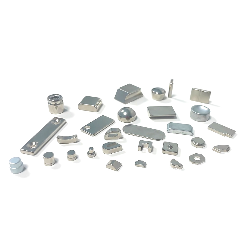
Custom geometries require special attention to the load line. Cutting away material to form chamfers, holes, or complex profiles changes the permeance coefficient and therefore moves the operating point on the loop. A magnet that was perfectly safe as a solid block may become vulnerable to irreversible demagnetization after a slot is added or a corner is removed. A supplier that can provide both loop data and custom shaping services is a genuine motor magnet supplier, because it evaluates the final geometry against the actual demagnetization curve rather than relying on handbook assumptions.
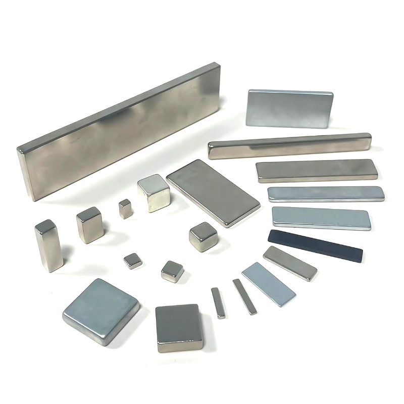
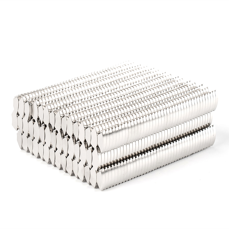 Custom-Shaped Neodymium Magnets for Special Motor GeometriesThis collection includes wedge, block-with-hole, hollow cylinder, stepped cube, and other irregular NdFeB shapes. The surrounding paragraphs stress how custom features alter the load line and permeance coefficient, making these geometries important for evaluating demagnetization risk in non-standard motor designs.View Product →
Wholesale buyers and motor manufacturers alike should remember that the highest-quality magnet is not necessarily the one with the highest (BH)max. It is the one whose loop stays square over the full operating range, whose batch-to-batch variation is small, and whose supplier can document every measurement. That combination of data and control is what turns a commodity component into a reliable, high-volume motor magnet.
Key takeaway: The strongest procurement strategy combines a high squareness ratio at temperature, full lot traceability, and direct manufacturer support for custom geometry and magnetization patterns.
What is a hysteresis loop in simple words?A hysteresis loop is the closed curve that shows how a magnetic material responds to a cyclic magnetic field. Because the material remembers its magnetic history, the curve on the way up does not retrace the curve on the way down. The gap between the two paths is hysteresis, and the full cycle forms a loop whose area represents energy lost as heat. |
Why do permanent magnets use only the second quadrant of the loop?A permanent magnet operates in the demagnetizing region where H is negative and B is still positive, which is exactly the second quadrant of the B-H loop. The second-quadrant curve, also called the demagnetization curve, determines how much flux the magnet supplies in the magnetic circuit and how strongly it resists being demagnetized by an external field. The first quadrant describes the magnetization process and is not used during steady motor operation. |
What is the difference between Hcb and Hcj on a NdFeB datasheet?Hcb is the reverse field needed to reduce magnetic flux density B to zero. Hcj is the reverse field needed to reduce intrinsic polarization J to zero, which represents the complete destruction of the material's magnetic ordering. Hcj is always larger than Hcb, and it is the more meaningful safety parameter for motor design because once J reaches zero, the magnet can no longer be restored without full remagnetization. |
How does temperature affect the hysteresis loop of NdFeB magnets?Both remanence and intrinsic coercivity decrease as temperature rises. Br drops roughly linearly at a rate of 0.09 to 0.12 percent per degree Celsius depending on grade, while Hcj drops at a higher rate. The knee of the demagnetization curve moves toward the operating point, which is why high-temperature grades with increased heavy rare-earth content are specified for motors that operate above 120 °C. |
Can a partially demagnetized motor magnet be remagnetized?Yes, by applying a magnetizing field strong enough to drive the material back into saturation. In practice, however, remagnetization inside an assembled motor is difficult because the magnetizing field must overcome the airgap and the surrounding steel path. Preventing irreversible demagnetization through correct grade selection and operating-point analysis remains the most reliable approach for motor manufacturers. |
What should I ask a magnet manufacturer about the hysteresis loop before placing an order?Ask for measured demagnetization curves at 20, 60, 100, 120, 150, 180, and 200 °C where relevant, along with Hcj, Hk, and squareness values for each curve. Ask which test method was used, whether the sample came from the same production batch that will be delivered, and how lot-to-lot variation is controlled. A manufacturer that can answer these questions with data is a stronger partner than one that only quotes a grade name. |
Key takeaway: The questions you ask about the hysteresis loop directly reveal the engineering discipline of the magnet supplier.
The hysteresis loop is not a classroom exercise; it is the operating contract between a permanent magnet and the magnetic circuit around it. Every torque ripple, temperature limit, energy loss, and demagnetization risk in a motor can be traced back to the shape of that loop and how it shifts with temperature. The motor engineer who reads the loop correctly avoids the most expensive failure in permanent magnet machines: irreversible loss of flux after the first overload event.
Before finalizing your next motor magnet order, compare the loop data of at least two manufacturers at the temperature your motor will actually see. Look for a square second quadrant, a high Hk/Hcj ratio, consistent batch-to-batch values, and a supplier willing to explain its measurement procedure. That is how a design team separates a reliable magnet source from a catalog reseller.
For the latest guidance on magnet applications, production technology, and material trends, follow our magnet industry news. And when your project demands measured hysteresis data at elevated temperatures, contact a NdFeB magnet manufacturer such as Ningbo Tujin Magnetic Industry Co., Ltd. to discuss your operating point, grade selection, and custom geometry requirements.
Key takeaway: Read the loop, at temperature, from the actual production batch; the magnet grade name is only the beginning of the story.
Having a blueprint in mind, working hard and forging ahead
 No.107 Yunshan Industry Park, Sanqishi Town, Yuyao, Ningbo, Zhejiang 315412, China
 +86-18858010843
 sales@tujinmagnet.com
Copyright ? Ningbo Tujin Magnetic Industry Co., Ltd. All Rights Reserved. Custom Rare Earth Magnets Factory